
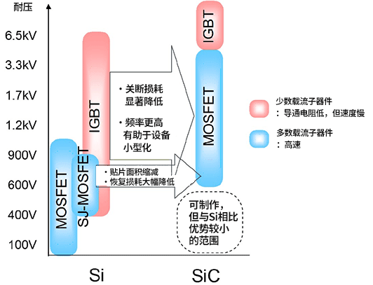
The chart below summarizes the characteristics of power devices with voltage ratings from 600V to 2000V.
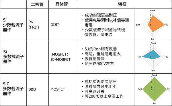
In the radar chart: RonA represents on-resistance per unit area (indicating conduction loss), BV is the device breakdown voltage, Err is the recovery loss, and Eoff is the switching-off loss. SiC devices already perform exceptionally and are not overestimated in current comparisons.
Comparison of Power Transistor Structures and Features
The chart below compares the structure, voltage rating, on-resistance, and switching speed of various power transistors.
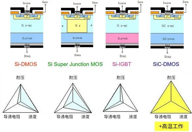
1.Different fabrication technologies result in different structures, leading to varying electrical characteristics.
2.DMOS is a planar MOSFET and a common structure. For high-voltage applications with reduced on-resistance, silicon power MOSFETs with Super Junction (SJ-MOSFET) structures have become increasingly popular in recent years.
Key Features:
1.Si-DMOS faces challenges with on-resistance, which can be improved using SJ-MOSFET structures. IGBTs perform well in on-resistance and voltage rating but are limited in switching speed.
2.SiC-DMOS excels in voltage rating, on-resistance, and switching speed, and maintains strong performance at high temperatures, making it a highly advantageous switching device.
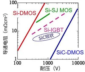
3.The chart shows normalized on-resistance versus voltage for various transistors. Theoretically, SiC-DMOS can achieve higher voltage ratings while maintaining low on-resistance.
Differences from IGBT: Vd-Id Characteristics
Vd-Id characteristics are a fundamental property of transistors. At 25°C, SiC and Si MOSFETs show a linear increase of Id with Vd (Vds), while IGBTs have a voltage drop at low currents, resulting in higher Vd in that range. According to Ohm’s law, lower Vd for the same Id means lower on-resistance.
IGBTs perform well in high-voltage, high-current applications, but efficiency is lower at low-power ranges. In contrast, SiC-MOSFETs maintain low on-resistance across a wider range.
At elevated temperatures (150°C), Si MOSFETs show increased on-resistance due to flatter Vd-Id slopes, while SiC-MOSFETs exhibit minimal change, keeping performance more stable with temperature.
与IGBT的区别:Vd-Id特性
Vd-Id特性是晶体管最基本的特性之一。下面是25℃和150℃时的Vd-Id特性。

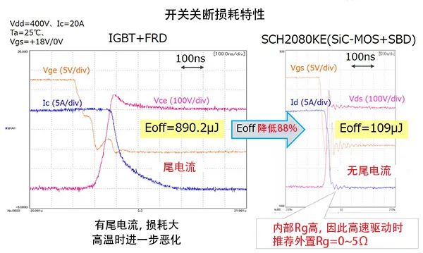
Differences from IGBT: Turn-off Loss
SiC power devices excel in high-power, high-speed switching. Unlike IGBTs, which exhibit tail current during turn-off leading to higher switching losses, SiC-MOSFETs have virtually no tail current, resulting in minimal turn-off loss.
For example, a SiC-MOSFET paired with an SBD (Schottky Barrier Diode) reduces Eoff by 88% compared with an IGBT + FRD (Fast Recovery Diode) combination.
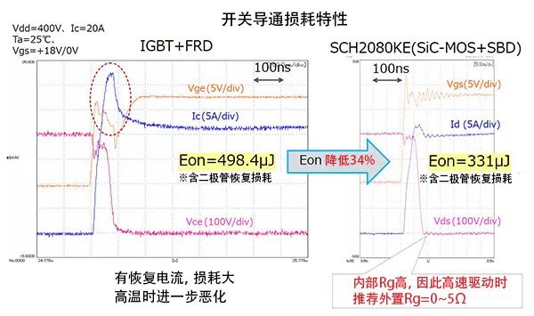
Differences from IGBT: Conduction Loss
During switching conduction, IGBTs experience significant loss due to diode recovery current flowing through Ic. In contrast, when using SiC-MOSFETs with a fast-recovery SBD, conduction loss is reduced thanks to the MOSFET’s fast recovery characteristics. For FRDs paired with IGBTs, conduction loss increases with temperature, similar to tail current losses.
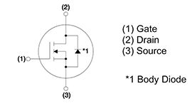
Body Diode Characteristics of SiC-MOSFET
SiC-MOSFETs feature a body diode between drain and source, formed by the MOSFET’s internal pn junction, also called a parasitic or internal diode. Its forward and reverse-recovery performance is a critical parameter, playing an essential role in practical applications.
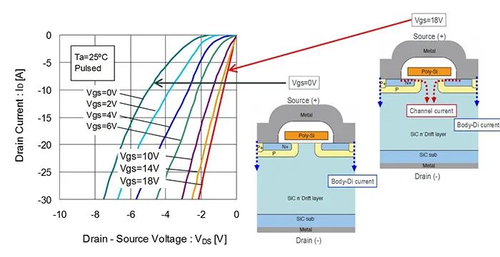
Forward Characteristics of SiC-MOSFET Body Diode
The Vds-Id characteristics of a SiC-MOSFET show that when a negative voltage is applied from source to drain (Vgs = 0V, MOSFET off), the body diode is forward-biased. The green curve at Vgs = 0V represents the diode’s Vf characteristic, as no channel current flows in the off state. Due to SiC’s wider bandgap, Vf is significantly higher than that of Si-MOSFETs.
When Vgs = 18V (MOSFET on), current mainly flows through the low-resistance channel rather than the body diode. A cross-sectional diagram of the MOSFET is provided to help visualize the different conduction states.
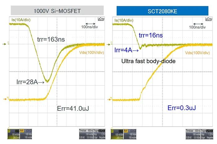
Reverse Recovery Characteristics of SiC-MOSFET Body Diode
Another key feature of MOSFET body diodes is the reverse recovery time (trr), an important parameter for diode switching performance. Since the MOSFET body diode is a pn-junction diode, it exhibits reverse recovery behavior characterized by trr.
The comparison below shows trr for a 1000V Si-MOSFET and the SiC-MOSFET SCT2080KE. The Si-MOSFET has a slower trr with higher Irr, while the SiC-MOSFET SCT2080KE’s body diode switches very fast. Both trr and Irr are nearly negligible, significantly reducing recovery loss (Err).
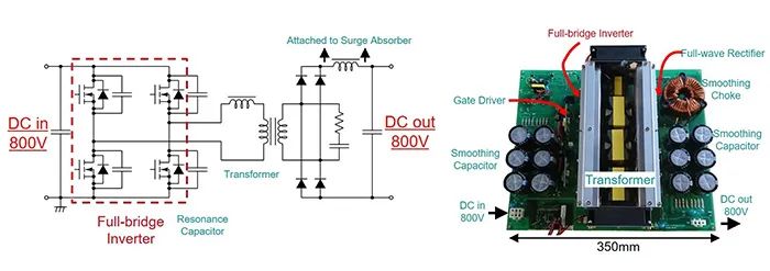
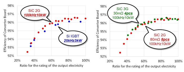
SiC-MOSFET Application Example 1: Phase-Shifted DC/DC Converter
The demonstration system was developed in collaboration with Power Assist Technology Ltd. A full-bridge inverter uses three types of transistors—Si IGBT, 2nd-generation SiC-MOSFET, and the 3rd-generation trench SiC-MOSFET introduced earlier—forming a phase-shifted DC/DC converter of the same size to compare efficiency.
SiC-MOSFETs leverage their superior switching performance to achieve high-frequency operation (100 kHz) and higher power levels that are difficult for Si IGBTs. In the 2nd-generation SiC-MOSFET, two transistors are paralleled per switch, whereas the lower on-resistance of the 3rd-generation SiC-MOSFET reduces the number of transistors from 8 to 4. Efficiency is highest with 3rd-generation SiC-MOSFETs, and all SiC-MOSFET configurations outperform Si IGBTs.

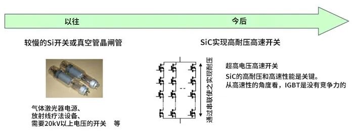
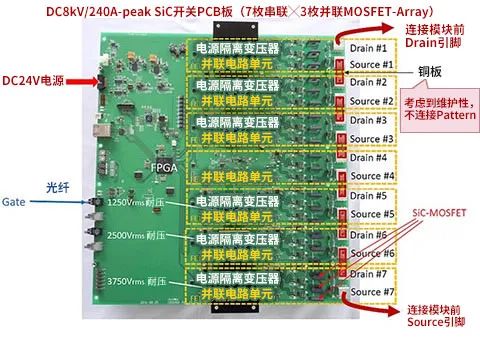
SiC-MOSFET Application Example 2: Pulse Power Supply
Pulse power supplies deliver short bursts of high power and are used in gas lasers, accelerators, X-ray systems, and plasma power sources. Traditional solutions include thyristors, vacuum tubes, and Si switches, but the market demands higher voltage and faster switching.
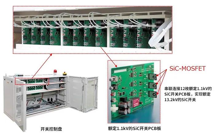
Leveraging SiC’s high voltage capability and fast switching performance, SiC-MOSFETs enable ultra-high-voltage, high-speed operation that is difficult to achieve with Si IGBTs.
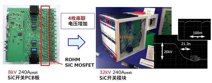
・1~10kV随机脉冲发生器:13.2kV SiC开关

 Wechat
 销售在线
销售在线 联系电话
联系电话